
InSight Instrument Overview
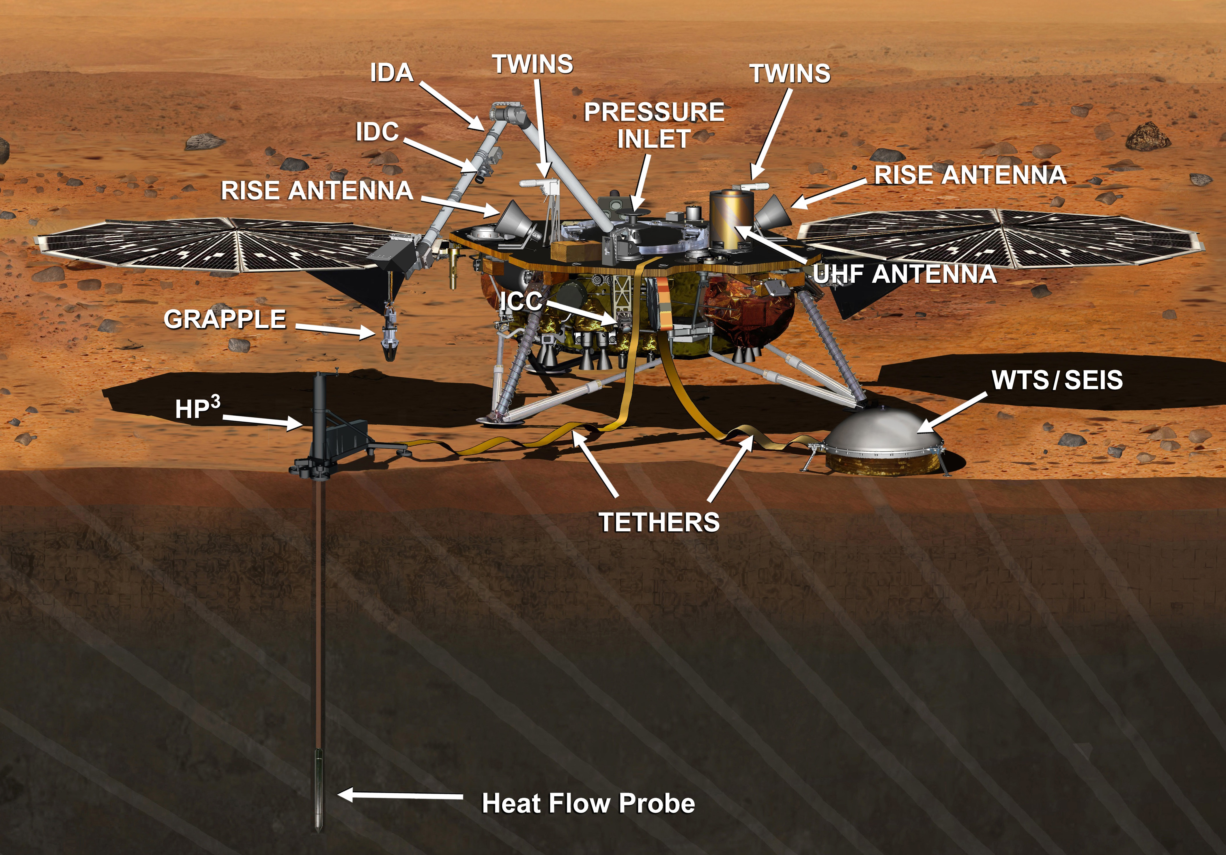
The Interior Exploration using Seismic Investigations, Geodesy and Heat Transport (InSight) Mission to Mars has three principal instruments designed to measure present-day seismic activity on Mars, quantify the outflow of heat from its planetary core and probe the interior by means of precise rotation and nutation measurements.
Additionally, the InSight Lander carries a weather measurement suite, a magnetometer to measure disturbances from the Martian ionosphere and a pair of cameras for documentation of instrument deployment and characterization of the landing site. Two of the principal science payloads will be deployed to the Martian surface by a 2.4-meter long robotic arm.
SEIS – Seismic Experiment for Interior Structure
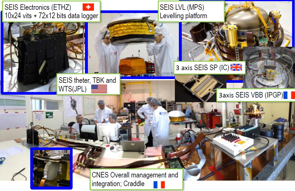
The SEIS instrument is the most sensitive seismometer ever deployed on an interplanetary mission, designed and built by the French Space Agency CNES with support from NASA JPL, Imperial College, UK, ETH, Switzerland and the Max Planck Institute, Germany. SEIS has sufficient sensitivity to detect ground movements the diameter of a hydrogen atom and will reveal details on the Martian interior by measuring seismic activity coming from the depths of the planet’s crust (Marsquakes) or tremors caused by meteorite impacts.
SEIS is not the first seismometer to fly to Mars, but it would be the first to fulfill its function if entering service after a successful landing. Two seismometers were landed on the Viking missions in 1976: the Viking 1 seismometer failed to deploy properly while data from the Viking 2 seismometer was not usable for seismic measurements due to its installation on top of the lander where external effects from wind and internal vibration from the lander systems severely degraded its performance.
Leveraging lessons learned from Viking, SEIS will be deployed directly to the Martian surface and a fully decoupled wind shield will provide further protection while weather sensors collect wind and temperature measurements to factor into seismometer data processing.
SEIS is a tripod-mounted seismometer specifically designed as a very broad-band and short-period instrument to cover a number of measurements. Its primary task will be the measurement of how tremors – either caused deep in the Martian crust or by meteorite impacts – propagate through the Martian interior to help reveal the planet’s internal structure. This will also shed light on the planet’s history and help address the question on the size and properties of Mars’ core. Also, SEIS can measure signatures of atmospheric waves, local storms like dust devils, gravitmetric signals (tidal forces) from Mars moon Phobos, and high-frequency seismic phenomena up to 50 Hertz.
The SEIS instrument was the major trouble-maker of the InSight mission, necessitating its original launch campaign toward a March 2016 liftoff to be abandoned when a persistent leak in the instrument’s vacuum enclosure could not be fixed. A high-quality vacuum around the seismometer’s sensors is paramount for SEIS achieving its science goals and a number of last-minute attempts to patch the leaky weld came up empty-handed.

After reviews, it was decided that InSight’s science goals were compelling and the mission was allowed to proceed with a revised launch date of May 2018 and a plan to have NASA’s JPL fully re-design the SEIS vacuum enclosure. The additional cost for delaying the mission by 26 months to the next planetary launch window raked up to $155 million including the instrument re-design, spacecraft storage and re-testing, shuffling Atlas V rockets, and keeping the mission and science team in place for an additional two years.
SEIS is based on a six-axis hybrid instrument using two different sensor types: three Very Broad Band (VBB) seismic probes reside in a tetrahedron configuration within the vacuum sphere and three Short Period (SP) seismic probes are installed around it. These are supported by various temperature and pressure sensors plus a myriad of electronics, power supplies, feedback boards for the sensors and the MDE deployment system. SEIS has a mass of 11.5 Kilograms and is capable of measuring accelerations down to 10-9 m s-² Hz-½ over frequencies of 0.001 to 10 Hz and 5 x 10⁻⁸ m s-² Hz-½ from 0.01 to 100 Hz.


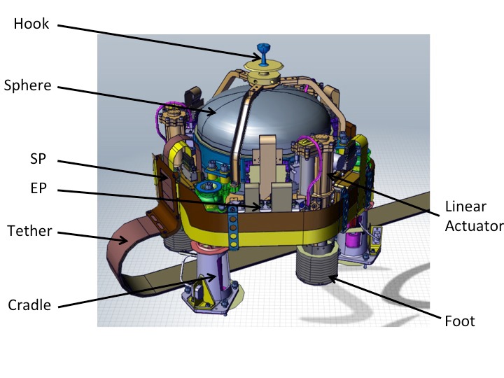
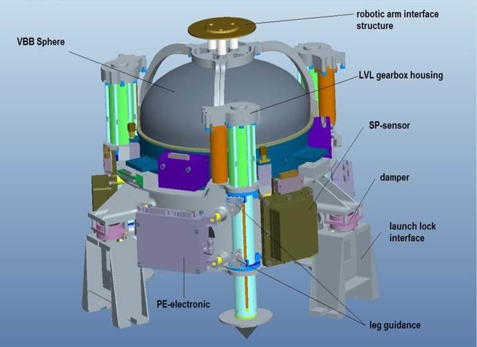
The SEIS sensor head weighs 8.5 Kilograms and is approximately 30 x 30 x 30 centimeters in size, featuring a hook on its upper face to interface with the InSight Instrument Deployment Arm to be lowered to the ground as part of the mission’s two-month commissioning phase.
Each of the VBBs is a leaf-spring inverted pendulum seismometer that employs a precisely defined test mass suspended on a pendulum and placed in motion by external inputs from the ground. Through highly precise Differential Capacitive Sensors (DCS) and electromagnetic feedback from the three VBBs, a three-axis representation of the ground motion can be reconstructed with nanometer precision.
The three short-period probes make use of silicon-based Micro Electro-Mechanical System (MEMS) accelerometers installed to measure acceleration in one vertical and two orthogonal horizontal directions.
They employ a mobile mass that is kept in a fixed position by means of a magnetic coil actuator coupled with a fast feedback loop that controls the current needed to keep the mass at the zero position. Acceleration along the MEMS sensitive axis is directly proportional to the current needed in the magnetic coil to keep the test mass centered. This type of device, while less sensitive than the VBB, can offer a much broader frequency range, especially in the high-frequency domain desired to be probed by SEIS.
One critical element of SEIS is its Leveling Subsystem tasked with establishing a good mechanical coupling between the ground and the instrument sensors while also ensuring the sensor package is precisely level on the ground to ensure its measurement axes are precisely aligned. This will require slopes of up to 15 degrees to be fully compensated by the three adjustable legs of the SEIS instrument structure which can be individually extended or retracted by up to six centimeters. Two redundant sets of precise inclinometers measure the instrument’s positioning to provide feedback to the leg actuators.

The three feet of the SEIS instrument have a cone-shaped section designed to sink into the Martian regolith to establish a good mechanical coupling with the surface to create stability while disks installed above the cones prevent further undesired surface penetration and increase the contact area between the instrument and regolith.
For launch, transit to Mars and landing, SEIS resides on three separate structural elements that incorporate dampening systems to reduce vibration loads transferred into the sensor package. Separation of the SEIS package is completed by frangibolt actuators.
The SEIS instrument package contains the Proximity Electronics Boxes for the VBBs and the integrated SP units while the rest of the instrument electronics reside within the Lander’s science deck, connected to the senor package through a flat cable harness which deploys as the package is lowered to the surface.
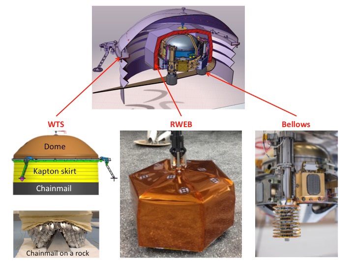
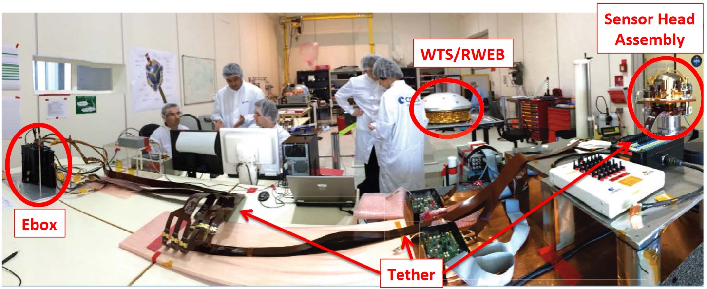
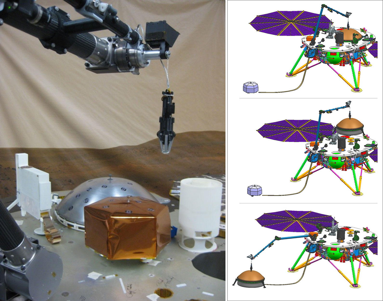
Deployment of SEIS is a two step process, starting with lowering the LVL Sensor Package to the ground followed by the careful lowering of the Wind and Thermal Shield (WTS) in a position to fully cover the LVL and protect it from wind vibrations and large temperature swings experienced between day and night. The WTS comprises an aluminum dome, a Kapton skirt on the bottom of the dome that fully lowers to the surface and three feet that provide proper mechanical contact with the surface and interface with the dome.
The Kapton skirt ends with multiple chainmail that makes it properly fit the ground even in the presence of rocks. The WTS dome is coated with silicon oxide that has a low infrared emissivity of 0.15 to 0.25 and solar absorptivity in the same range. Internally, the WTS dome and skirt are coated with Vapor Deposited Aluminum (VDA) to reduce radiative heat leaks. Due to the sizing of the WTS, a portion of Martian surface around the LVL sensor is also protected and provides an additional source of thermal inertia to reduce the daily temperature variation on the sensors.

The LVL Sensor Package itself is further protected by a Remote Warm Enclosure Box (RWEB) consisting of two Mylar sheets with a two-centimeter gap that will fill with Martian atmospheric gas (mainly CO2) which will be mostly motionless and provide an additional thermal insulation layer due to the low thermal conductivity of carbon dioxide. Internally, the RWEB is also coated with VDA while the external face uses Kapton to prevent overheating during the deployment phase.
The vacuum sphere is a third layer of thermal protection for the VBB sensors and titanium washers provide isolation of the sensors from thermal variations on the sphere itself.
The 3-Kilogram SEIS E-Box resides within the warm compartment of the InSight lander and interfaces with the LVL package through the tether. It comprises two redundant acquisition and management units based on Field Programmable Gate Array technology and 24-bit analog-to-digital conversion for the acquisition of science data.
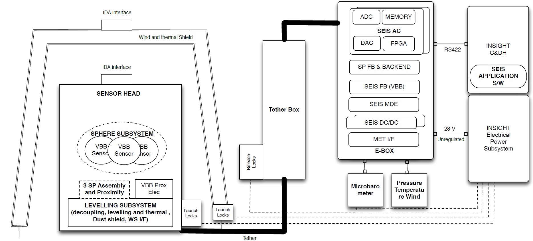
A dedicated instrument memory stores the science data before transmission to the Command & Data Handling Unit through a serial RS-422 data bus. The E-Box also accepts the 28-Volt unregulated power bus from the spacecraft and converts it to the various operational voltages of the instrument and a dedicated MET Interface board receives data from the environment sensors installed on the Lander Deck.
Meteorology support is a critical element for seismic investigations as shown by the Viking seismometers that were not able to deliver useful data in part due to problems subtracting wind influence from the instrument readings. InSight will mitigate wind effects to a much larger degree than Viking by placing the seismometer directly on the ground and isolating it physically from thermal and wind influence. Nevertheless, local wind and temperature perturbations are still expected to affect the SEIS measurements and will require precise monitoring to be factored into data processing and analysis.
To that end, InSight carries a suite of wind and air temperature sensors with heritage from the Mars Science Laboratory Rover Environmental Monitoring System developed primarily by CAB, Spain, plus a highly sensitive Tavis pressure sensor. Although the meteorology suite is primarily used for the correction of SEIS data, it will also deliver scientifically valuable data for assessments of the Martian surface environment, continuing a multi-year weather record and collecting simultaneous measurements with the MSL rover that operates only 600 Kilometers from InSight.
The Pressure Sensor has a quad-disk inlet similar to those on Earth-based infrasound detectors to be able to isolate atmospheric pressure changes from wind-induced pressure fluctuations. It obtains 20 pressure samples per second at an accuracy of approximately 5 mPa which will enable the instrument to detect infrasound events from meteorite impacts and other sources – opening a new field of study for Mars surface missions.

TWINS – the Temperature and Wind for InSight Suite – is a re-packaged version of the MSL REMS wind and air temperature sensors, installed on roughly opposite sides of the lander and facing outward to capture wind speed and directional data.
Air temperature is measured with a pair of PT1000-type sensors installed on a small rod that takes the sensor out of any thermal boundary layers of the lander. Their measurement range is 150 to 300 K and they deliver measurements at a frequency of 1 Hz with a resolution of 0.1 K and absolute accuracy of 5 K. The use of two thermistors installed at different distances on the rod enables an absolute air temperature measurement through subtraction of heat convection and conduction within the structural element that is connected to the warm lander body.
Borrowed from REMS, the wind sensors employ thermal anemometry to record the wind speed. Hot wire anemometry measures the amount of power required to heat a wire so that it maintains a constant temperature difference with the ambient temperature in the fluid wind environment. This can also be achieved by measuring the temperature profile of a wire while using a constant amount of power to heat it and calculating the convective power to deduce wind speed. REMS uses a titanium thin film resistors patterned on the surface of a silicon chip instead of wires.
The wind sensors are sampled once per second and deliver an accuracy of ±40% for slow winds up to 3.5 meters per second and ±15% for faster wind speeds.
In addition to the pressure, temperature and wind sensors, InSight will employ its arm-mounted camera to measure atmospheric opacity and monitor clouds.
One unique aspect of the meteorological measurements provided by InSight is their continuous nature since an unbroken record is needed for SEIS characterization. Other environmental instruments like REMS only operate for a given duty cycle based on power requirements and science objectives. A continuous record may reveal rare phenomena missed in previous missions and characterize known phenomena in greater detail, thus adding scientific value to instrumentation initially only intended to help the seismic mission objectives.
Additional characterization data for SEIS is provided by a fluxgate magnetometer with an accuracy of 0.1 nano-Tesla to look into effects of ionospheric disturbances on seismic measurements.
HP³ – Heat-Flow and Physical Properties Probe
HP³, the Heat-Flow and Physical Properties Probe, is a burrowing heat probe designed by the German Aerospace Center to penetrate three to five meters into the Martian surface through the use of a self-hammering mechanism and so deploy a series of temperature sensors to different depths to measure the outflow of heat from the Martian interior.
Measuring the flow of thermal energy will provide extremely valuable insight into the planet’s thermal history which in turn will reveal general knowledge on the formation and evolution of rocky planets throughout the universe.
Understanding the thermal history of Mars will also reveal how the planet lost its protective magnetic field which set in motion a million- or billion-year process of Mars slowly losing its atmosphere and turning from a planet capable of harboring life to the deserted world we see today.
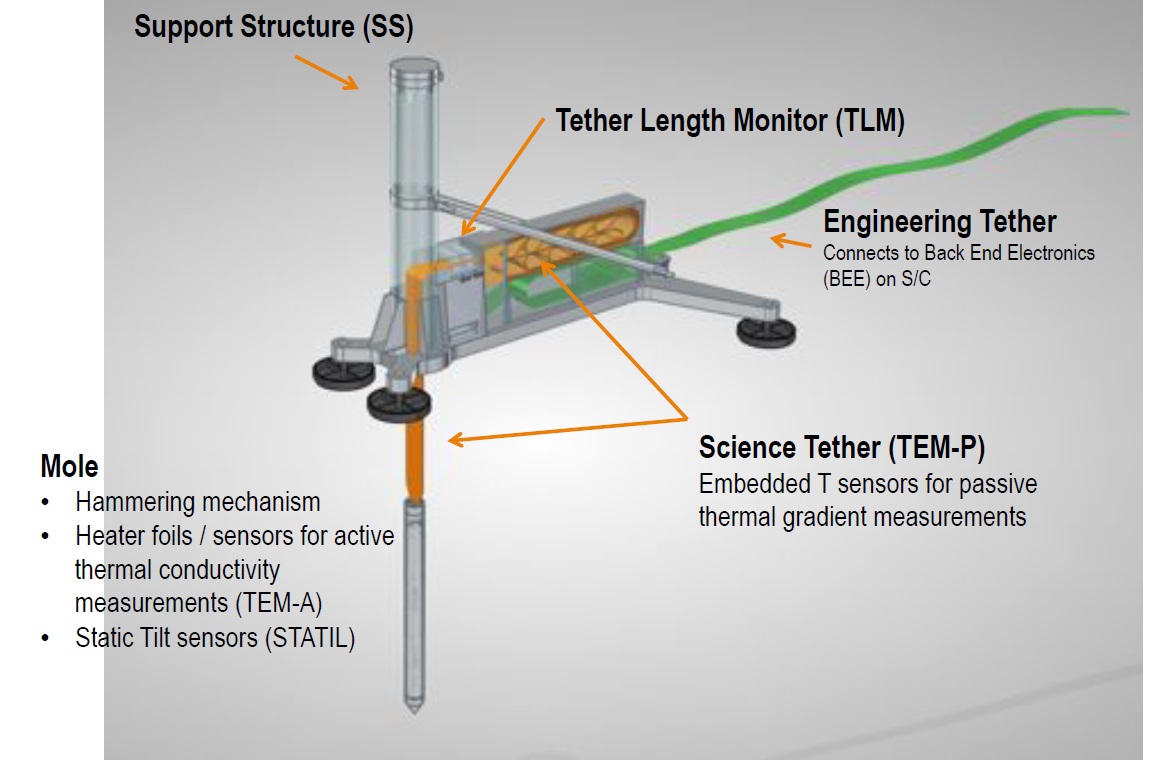
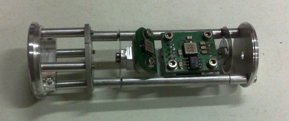
Nicknamed “the mole,” the core component of the HP³ package is outfitted with an active and passive Thermal Measurement Suite (TEM-A and TEM-P) and a combined accelerometer and tiltmeter (ACTIL). An internal hammering mechanism utilizing two spring-loaded masses is designed to propel the mole through several meters of Martian regolith.
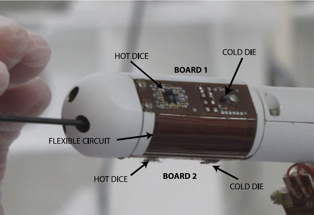
Thermal probes are installed every 35 centimeters along the five-meter flat ribbon cable known as the Science Tether and designed to measure the temperature gradient along the borehole. Surface heat flow will be measured by determining the thermal conductivity of the Martian regolith and the thermal gradient which will be complicated by the seasonal variation of surface temperatures.
The mole design goes back to the PLUTO mole (PLanetary Underground Tool) developed for the unsuccessful Beagle-2 mission. An evolved design was manifested to fly as part of the Humboldt experiment package on the ExoMars mission which was canceled in 2009 as part of the reformulation of the ExoMars mission concept. HP³ was selected by NASA as a payload for the InSight lander in 2012 since the development work completed under ExoMars already advanced to a detailed instrument concept ready to press into manufacture and testing.
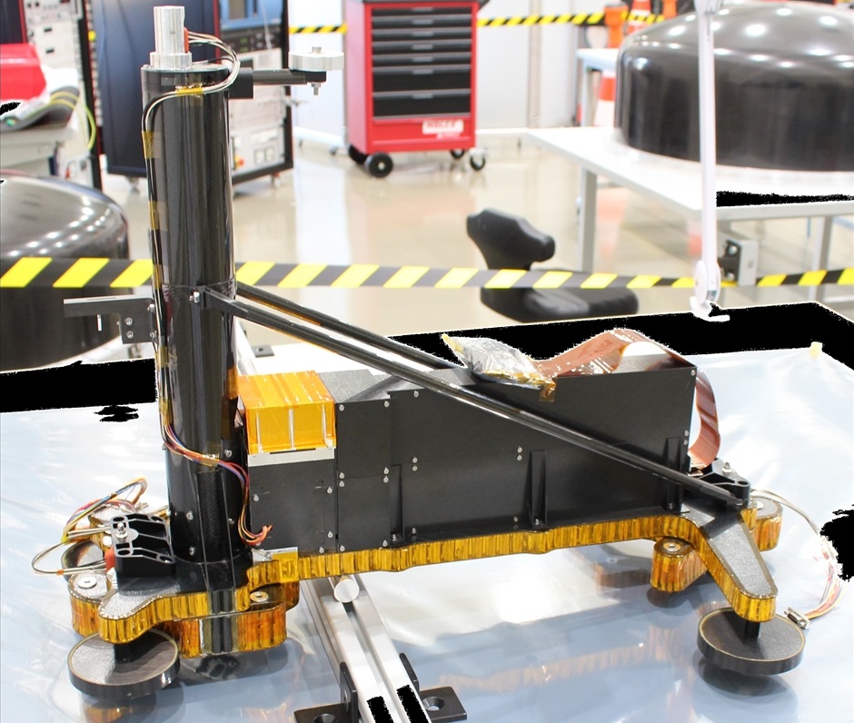
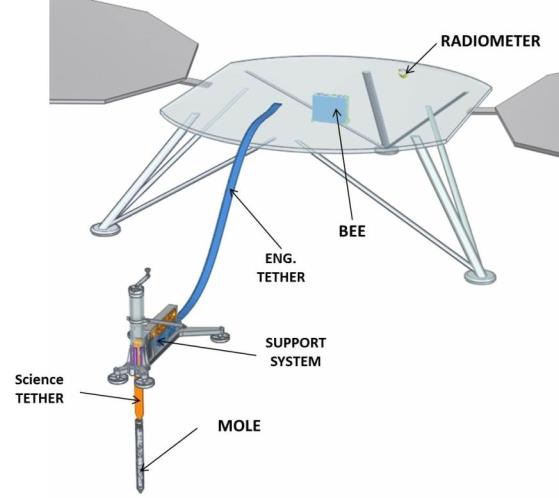
The HP³ instrument consists of a structure made of lightweight Carbon-Fiber Reinforced Polymer material to form the Science Tether Storage Compartment that holds the five-meter long mole tether, and the Mole Storage compartment responsible for securing the mole and releasing it for its burrowing mission.
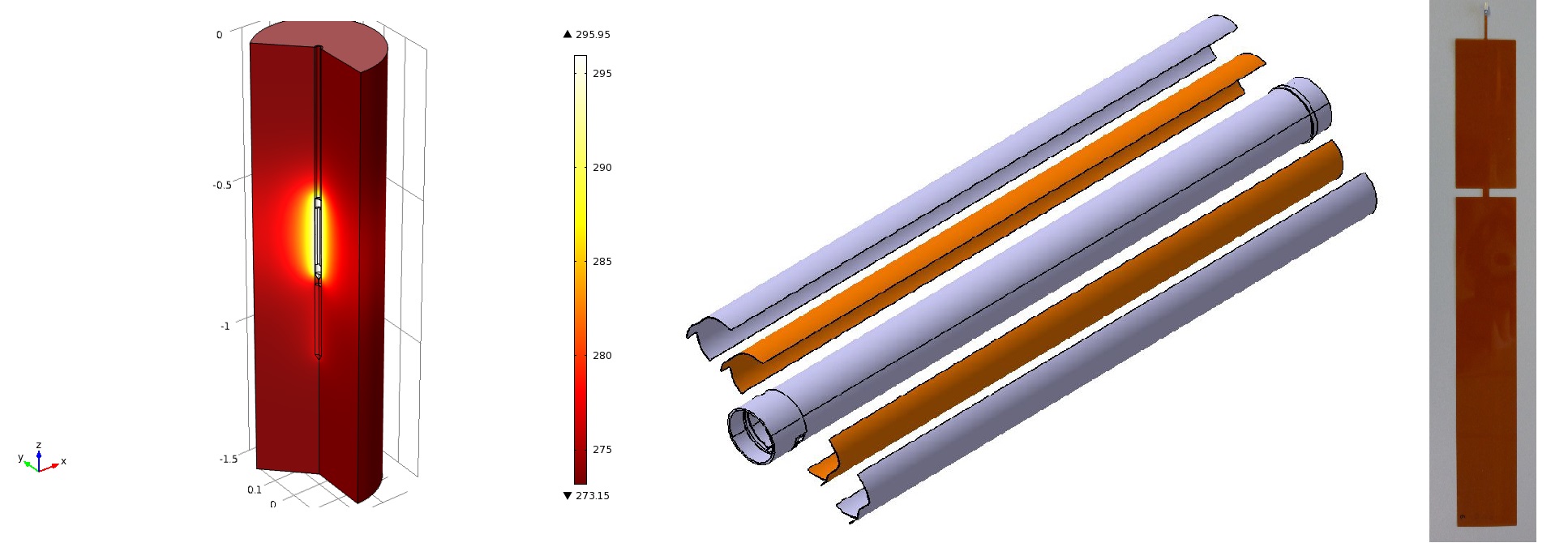
The surface package is connected to the InSight lander through an Engineering Tether that carries electrical power, commands, housekeeping and science data between the Lander and surface package. Within the cylindrical mole body resides the self-hammering mechanism and a series of thermal sensors and heating foils that will be used to determine the thermal conductivity of the regolith by operating the mole as a modified line heat source.
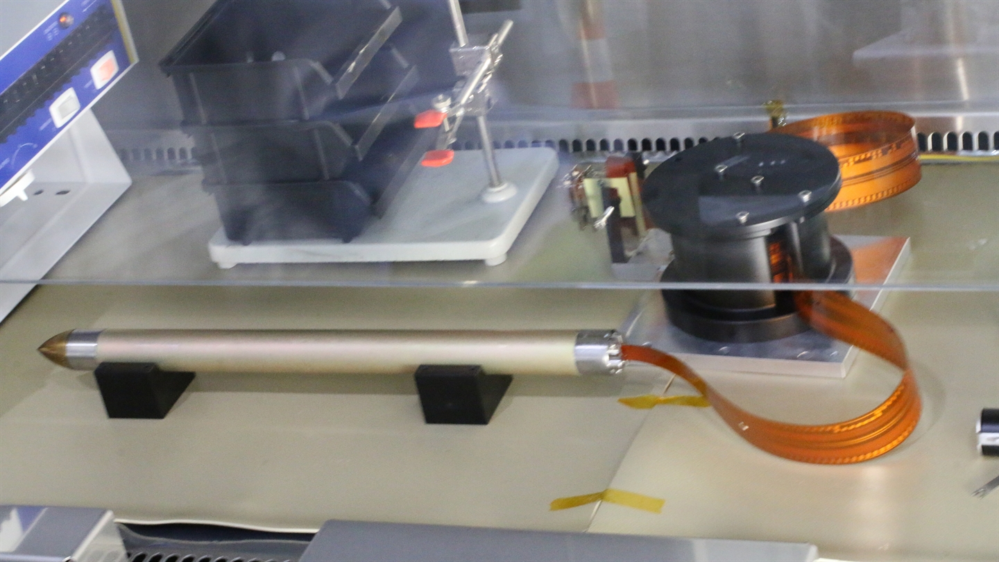
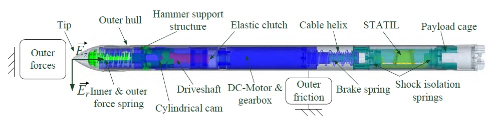
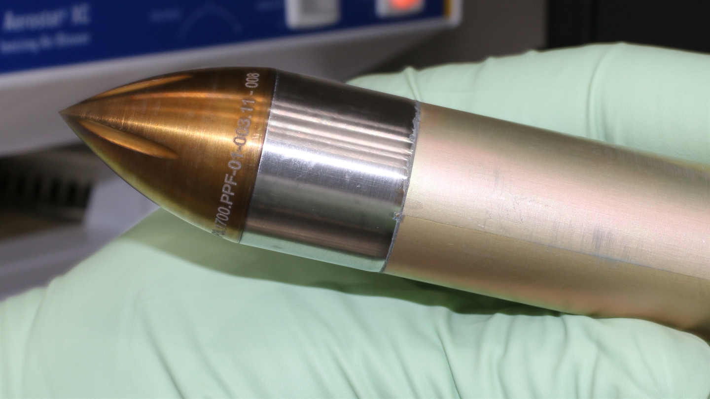
The mole is 39.6 centimeters long and 2.7 centimeters in diameter, featuring a conical tip and a hollow cylindrical body that contains the hammering system and the various sensors. The interior of the mole can be broken down in three sections: the hammering mechanism, the Active Thermal Measurement Suite (heater foils and sensors), and the Static Tilt Sensors (STATIL) residing in the upper part of the mole’s body. Damping springs are installed between the hammering mechanism and the sensing equipment to lessen the loads transferred to the instrumentation.
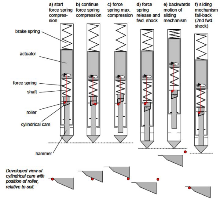
The electro-mechanical hammering system comprises a motor, gearbox, driveshaft, hammer and several springs which are compressed and released periodically to move a pair of hammer masses approximately once every 3.1 seconds. Action by the motor raises the two test masses and tension their respective springs until each is released and impacts the external hull of the mole, resulting in two discrete hammering actions per cycle to propel the probe into the granular subsurface material. The hammering cycle itself lasts no more than 200 milliseconds and drives the mole forward anywhere between 0.1 to 1 millimeter per stroke depending on its depth.
As the mole penetrates, it drags the science tether behind it, allowing the Tether Length Monitor (TLM) to act as a secondary measurement of penetration depth. The TLM employs two strings of markers on the science tether and an opto-electronic read-out device to count the passage of the markers to allow the deployed science tether length to be determined.
Each hammering cycle, constrained by power availability has a goal of advancing the mole’s depth by 50 centimeters followed by a pause for a thermal conductivity measurement of the surrounding regolith. This pause begins with a 48-hour period for heat from the hammering & penetration to fully subside before a 24-hour conductivity measurement cycle.
The regolith conductivity measurements will be taken through the transient hot wire method – injecting a known quantity of heat via the thermal foil heaters of the hull of the mole and then measuring the temperature as the heat dissipates into the surrounding regolith to infer the conductivity of the material.

Extensive work was completed to look into the effects of regolith density alteration by the mole hammering action on its thermal conductivity and develop correction algorithms for data obtained through the TEM-A system. Additionally, a secondary measurement of thermal conductivity will come through the TEM-P system’s determination of thermal diffusivity obtained from the attenuation of the annual temperature wave as seasons change.
The TEM-P system comprises fourteen PT100 temperature sensors soldered onto the five-meter long science tether to deliver temperature measurements as a function of depth (with a depth resolution of 35 cm) in order to determine the thermal gradient from which the heat flow from the Martian core can be calculated. The science tether itself is 3.5 centimeters wide – slightly wider than the diameter of the borehole to ensure sufficient thermal contact between the tether and the surrounding regolith.
In addition to the two TEM subsurface sensors, HP³ features a deck-mounted radiometer for the measurement of the local surface temperature in an unshadowed area unobstructed by hardware. The radiometer measures the surface flux in three thermal infrared wavelengths with two redundant channels per wavelength. The multi-wavelength measurement also allows for a long-term study of thermal properties of the surface and immediate subsurface, especially relevant when disentangling the diurnal and seasonal atmospheric forcing from the geothermal gradient.
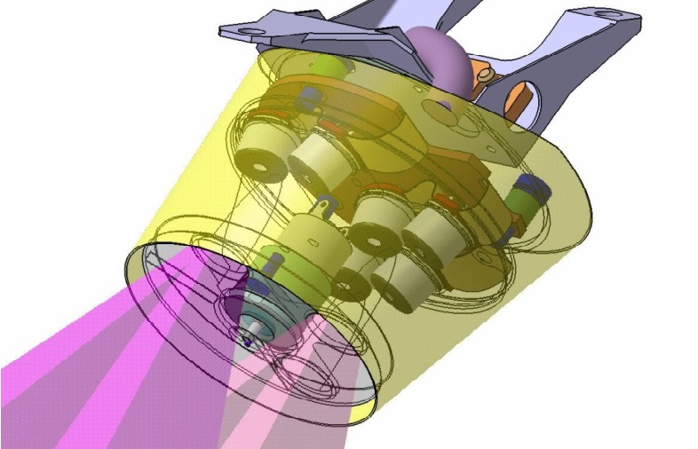
The radiometer enclosure, machined from aluminum, is installed below the lander deck and the thermopiles are oriented to observe two 20-degree cones towards north-north-west (lander coordinates), away from the workspace of the SEIS and HP³ deployment locations to keep hardware out of the FOV and avoid the shadow from the solar arrays for most solar geometries throughout the year.
The wavelength channels of the radiometer include a broad-band channel from 6µm, a narrow filter from 7.8 to 8.6 µm, and a filter tuned to the carbon dioxide band at 15µm to measure the atmospheric temperature. Internal heaters are employed to keep the instrument temperature constant and reduce noise.
RISE – Rotation and Interior Structure Experiment
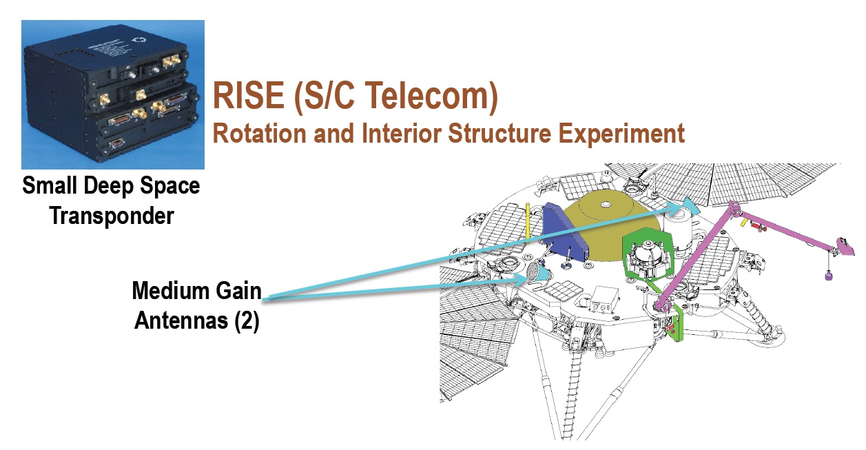
RISE is an X-Band Doppler Tracking Experiment to precisely measure the planetary rotation rate of Mars as well its variations (e.g. nutation). Such measurements were also taken by the Viking missions in the 70s, Pathfinder in 1997 and intermittently by the Mars Exploration Rovers.
The new set, extending the observation arc to four decades, will allow the nutation amplitude, spin axis direction and precession rate to be constrained very narrowly to allow for a conclusive determination of Mars’ core size and whether it exists in liquid or solid form.
For the RISE study, the baseline lander and spacecraft design employed by NASA’s Phoenix was changed in that an X-Band Small Deep Space Transponder (SDST) was moved from the Cruise Stage to the Lander while a Solid-State Power Amplifier was added to keep up Cruise Stage redundancies while also enabling the lander to operate as a fully equipped transmitter once on the surface.

The SDST and SSPA are coupled to a pair of redundant Medium-Gain Antennas used to receive and transmit the 7.152/8.402 GHz signals for the RISE experiment. The MGAs reside on opposite sides of the lander to provide omni-directional azimuth coverage for an elevation range between 30 and 55 degrees to allow for continuous tracking when Earth is at low elevation (when the Doppler signature due to the rotation of Mars is largest).
The basis of RISE is widely used for deep space navigation: an X-Band equipped ground station sends a signal to the spacecraft which immediately re-transmits it to Earth where its Doppler Shift can be analyzed to reveal the exact relative velocity between Earth and the lander on the surface of Mars. Data correction for signal re-transmission delays intrinsic to the lander electronics will increase accuracy to around two centimeters and a long observation arc will further help nail down the exact rotation and precession parameters sought by scientists.
Doppler Measurements from Viking and Pathfinder helped scientists constrain Mars’ core size and precession rate which confirmed that Mars has undergone a history of differentiation. Subsequent Doppler measurements carried out by orbiting missions like the Mars Global Surveyor, Mars Odyssey and the Mars Reconnaissance Orbiter provided additional information for narrowing down the precession parameters through effects of the Martian gravitational field on the spacecraft orbits. However, the detection of the nutation signature is not possible from orbit.
Obtaining the nutation of the spin axis will provide the last piece needed for assessing the nature of the Martian core. If the core is fluid, as suggested based on previous data, then the nutation will show a signature of the polar moment of inertia of the core and the free-core nutation period which will also provide information on the size and shape of the core. In addition to nutation values, RISE will also be capable of measuring small variations in Mars’ rotation rate due to the exchange of carbon dioxide between the atmosphere and the polar ice caps as seasons change.
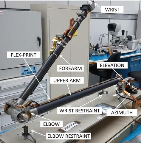
Instrument Deployment Arm
The InSight Instrument Deployment Arm (IDA) is a specialized lightweight robotic arm tasked with retrieving the SEIS LVL instrument package, the SEIS wind shield and the HP³ instrument package from the InSight lander deck and placing them on the surface of Mars to conduct their missions. Designed and built by MDA, the robotic arm finds its roots back in the 1990s when design work started for the canceled Mars 2001 Surveyor mission.
The IDA used on InSight is in fact that built for Surveyor, being pulled from long-term storage to finally receive a chance to operate on Mars.
Its design is essentially the same as that for the MVACS experiment sent to Mars in 1998 on the ill-fated Mars Polar Lander mission. A re-build of the arm was selected for the Surveyor mission and MDA US Systems (then Alliance Space Systems Inc.) delivered the arm in 1999 for system level testing and integration on the spacecraft. Shortly after the arm was delivered, Surveyor was canceled and the hardware was placed in a sealed shipping container with a standard atmosphere.
With formulation of the InSight mission in concepts and selection of the design in 2012, the old Surveyor arm was resurrected by MDA and put through a refurbishment and re-testing campaign of all actuators and related systems. One challenge when working with the 13-year old arm was that the software used to design it had not been used for over a decade and relied on 2D and 3D wire-frame techniques instead of solid 3D modeling.
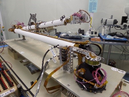
IDA is a two-segmented, three-jointed arm with motors – possessing an elevation & azimuth joint at its base on the lander deck (shoulder); an elbow hinge connecting the upper and lower arm and a wrist joint on the free-flying end. This four-degree-of-freedom design relies on four actuators, a lightweight interconnecting structure, multiple layers of flex-print with around 130 conductors and a self-actuated launch and landing restraint system. The entire arm assembly (minus end effector and payload) has a mass of only 3.4 Kilograms and is sufficiently strong to lift the InSight Payloads (up to 8.5 kg) onto the Martian surface.
The shoulder and elbow joints share a common architecture of motor/planetary gearbox/harmonic gear/output bearing while the wrist actuator differs by replacing the harmonic gear with a bevel gear pair. All are driven by ATC motors with graphite brushes – a design now considered antiquated as brushless motors have become the norm on interplanetary missions due to their longevity. However, at the time the arm was designed, brushed motors were preferred for their design simplicity and flight heritage. Given the limited use of the InSight arm during the mission, degradation experienced by the brushed motors is not a factor.

The ATC motors have iron core rotors with natural detent torque that provides the joint-holding torque when the actuators are powered off. All motors are outfitted with thin-film heaters employed during warm-up sequencing before arm use while PT thermal sensors provide feedback to the heater circuits.
Planetary gearing employed by the motors is based on modified commercial components with reduced ring-gear cross sections for mass-saving purposes. Planetary stage 1 and 3 in the shoulder and elbow actuators use small ball bearings; stages 1-3 in the wrist actuator incorporate similar bearings. The other stages have brushings and posts in use when gearbox torque transitions into higher levels. The harmonic gear elements are made of commercially available materials while the bevel gear in the wrist is custom-made. All actuators employ integral ball bearings consisting almost entirely of aluminum for further mass saving.
The IDA shoulder supports a 284-degree range of motion on azimuth and 215° on elevation, the elbow hinge can rotate by 285 degrees and the wrist by 215°. Absolute position feedback for each actuator is provided by a 50 kOhm conductive plastic potentiometer; an optical system comprising a photo-transistor, photo-diode and beam-breaker coupled to the motor shaft is tasked with guiding the fine-positioning of the arm.

The structure of the arm segments themselves consists of tubes made of XN-70 carbon fiber composite for the upper arm and XN-80 for the forearm with respective thicknesses of 0.8 and 1.1 millimeters. Their end fittings are thin-walled titanium bonded to the tubes with adhesive.
The major change on the Surveyor arm for InSight is the addition of a grapple mechanism capable of attaching and detaching from the SEIS and HP³ payloads to deliver them to the Martian surface. The grapple is attached to the arm wrist assembly via a soft coupling and has its own launch restraint on the lander deck.
The IDA launch restraint system is deliberately minimalistic under the overall mass-saving architecture of the integrated system. It consists of a passive 2-DOF elbow restraint and a spring-loaded 2-DOF wrist restraint to fully secure the arm and its actuators at launch with the exception of the output stage of the wrist joint. For release of the locks, a rotating cam surface on the wrist end-effector is driven to press on a mechanical trigger on the wrist to unlock the restraint.
Cameras
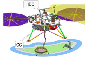
Unlike the Mars Exploration Rovers and the Mars Science Laboratory Curiosity Rover that actively explore Mars and ‘look’ at objects of interest through a number of cameras, InSight will be tasked with probing the interior of the planet for which no camera vision is needed. As such, InSight only carries a pair of cameras – one installed on the Instrument Deployment Arm to monitor and guide the transfer of the surface payloads and one installed on the lander body underneath the top deck. These are referred to as the Instrument Deployment Camera (IDC) and Instrument Context Camera (ICC), respectively.
The primary objectives of the two InSight cameras are threefold: 1) support the assessment of the surrounding terrain for the selection of SEIS and HP³ deployment locations, 2) guide and document the deployment activity, and 3) monitor the state of the instruments after deployment. Secondary non-engineering objectives will use the cameras for geological characterization of the landing site, collection of panoramic and stereo images with the arm camera and a long-term monitoring activity of atmospheric opacity and cloud movement with the IDC.

Both InSight cameras were sourced from the flight spare inventory of the Mars Science Laboratory which had flown build-to-print copies of the Mars Exploration Rover cameras as its navigation and hazard avoidance cameras. One major modification to the grey-scale cameras was replacing their detectors with a Bayer RGB color filter array version of the same detector.
Both cameras use identical Charged Coupled Device detectors 1024 x 1024 pixels in size with 12µm square pixels, a 12-bit ADC read-out and a read out time of 6.3 seconds. The exposure time can be set between zero and 406 seconds in increments of 6.2 milliseconds. Other than the CCDs, the camera electronics and optical assemblies were not changed from the MSL system and both cameras have identical camera heads, differing only in the type of lens.
The Instrument Deployment Camera (IDC) is installed on the forearm segment of the Instrument Deployment Arm. It is the MSL NavCam flight spare #210 and hosts a medium-field-of-view f/12 lens, creating a 45 x 45-degree FOV and an angular resolution of 0.82 mrad/pixel, typically translating to 1 mm/pixel at typical ground standoff distances. It has a focal length of 14.67 millimeters and a 1.25 mm entrance pupil.
The IDC is installed to have the scoop and grapple fixture on the end of the robotic arm in its field of view and the range of motion on the arm can position the camera to capture imagery of the lander deck, the foot pads, various geological targets in the immediate vicinity of the instrument worksites and the sky for cloud observations. The IDC has a depth of field from 0.5 meters to infinity with an optimized focus point at one meter for the documentation of the surface package deployment.
The Instrument Context Camera, MSL HazCam spare #203, is equipped with an f/15 fisheye lens with a 124 x 124-degree field of view with an angular resolution of 2.1 mrad/pixel. It can focus from 0.1 meters to infinity and its best focus point is at 0.5 meters to provide sharp images of the surface instrumentation packages for monitoring purposes.
All imagery generated by the two cameras is processed by the lander flight software. Acquisition is completed in a two-step fashion, starting with the collection of the actual image followed by a shutter image that is subtracted from the image of interest to remove readout smear and dark current. The raw Bayer image is then de-mosaicked into RGB triplets color-balanced based on color correction coefficients stored onboard. The resulting images are put through JPEG compression to reduce data volume before downlink to the ground. Given the cameras flight-proven nature, their ground processing segment can use existing architecture from MER and MSL.
