

SSGT Roland Downs adjusts the radio mast on Heaven’s Above (42-97328, 388BG)
Charlie Liberto, our radio restoration expert, came to us highly recommended from the Asheville Radio Museum and has thrown himself into the daunting task of rebuilding Lucky Thirteen‘s radio equipment. While it is not uncommon for antique aircraft to be restored using damaged or even hollow radios, we at Hangar Thirteen intend for Lucky Thirteen‘s radio complement to be fully functional. Part of our unparalleled commitment to accuracy, we feel that functional equipment is crucial to giving an appreciation of aerial warfare in the Second World War. Aircraft of the 1940s were anything but crude, and the miles of wiring that powered the B-17’s radio equipment are witness to that fact.
This will not be an easy task. True, the HAM radio community has gone far to preserve such equipment, however, this has proven to be a double-edged sword. While this means that many needed radio examples still exist, it also means that we face stiff competition from others who seek the same equipment for personal use. As such, we highly encourage any and all radio enthusiasts to contribute to our cause. From the radio unit, to the shock mount, to the wiring itself – it is all vital.
Blueprint 15-10987 Wiring Diagram (Master)
Blueprint 55-7789 Radio Equipment
Blueprint 55-7774 Radio Antennas
Blueprint M-1784 Radio Antennas (Modified)
In terms of wiring, the wires were covered with off-white colored cloth. So far, we have found figures on a few of the systems (which are noted below) and these figures total to:
6 Gauge Wire – 76.25 Inches (Approx. 6.5 Feet)
12 Gauge Wire – 486 Inches (Approx. 41 Feet)
14 Gauge Wire – 40 Inches (Approx. 3.5 Feet)
16 Gauge Wire – 636 Inches (53 Feet)
18 Gauge Wire – 9,678 Inches (Approx. 808 Feet)
20 Gauge Wire – 30,334 Inches (Approx. 2,530 Feet)
High Tension Wire – 24 Inches (2 Feet)
Likewise, several of the radios used splined tuning shafts, similar in appearance to old speedometer cables. The following lengths are called for:
Command Radio
Type MC-215 – 214 Inches (Approximately 17.8 Feet) (BC-455 to BC-450)
(16 ft piece) DONATED BY JACK ANTONIO (WARNER-ROBINS, GEORGIA)
Type MC-215 – 221 Inches (Approximately 18.4 Feet) (BC-454 to BC-450)
(16 ft piece) DONATED BY JACK ANTONIO (WARNER-ROBINS, GEORGIA)
Type MC-215 – 228 Inches (Approximately 19 Feet) (BC-453 to BC-450)
(16 ft piece) DONATED BY JACK ANTONIO (WARNER-ROBINS, GEORGIA)
Reel Antenna
Type MC-215 – 127 Inches (Approximately 10.6 Feet) (BC-461 to Antenna Reel)
(11 ft piece) DONATED BY JACK ANTONIO (WARNER-ROBINS, GEORGIA)
Radio Compass
Type MC-124 – 23 Inches (Approximately 1.9 Feet) (BC-433 to T)
(2 ft piece) DONATED BY JACK ANTONIO (WARNER-ROBINS, GEORGIA)
Type MC-124 – 20 Inches (Approximately 1.7 Feet) (T to Nav. BC-434)
(2 ft piece) DONATED BY JACK ANTONIO (WARNER-ROBINS, GEORGIA)
Type MC-124 – 97 Inches (Approximately 8.1 Feet) (T to Pilot BC-434)
(13 ft piece) DONATED BY JACK ANTONIO (WARNER-ROBINS, GEORGIA)
(6 ft piece) DONATED BY KARL WHITCHURCH (MILWAUKEE, OREGON)
The Boeing B-17F Flying Fortress came equipped with these radio components as standard:

GYRO FLUXGATE COMPASS
! ALL BASIC COMPONENTS COMPLETED !
Blueprint 9-5889 Gyro Fluxgate Wiring Diagram
Blueprint 15-10429 Gyro Fluxgate Compass Installation
Gyro Fluxgate Compass Basic Layout
AN5752 Indicator COMPLETE
AN5753 Amplifier DONATED BY JOE MCKOWEN (GAFFNEY, SOUTH CAROLINA)
AN5754 Caging Unit COMPLETE
AN5756 Switch Box DONATED BY B-17 COCKPIT PROJECT (ABRAINTREE, UK)
AN5757 Transmitter COMPLETE
AN5730 Repeater COMPLETE

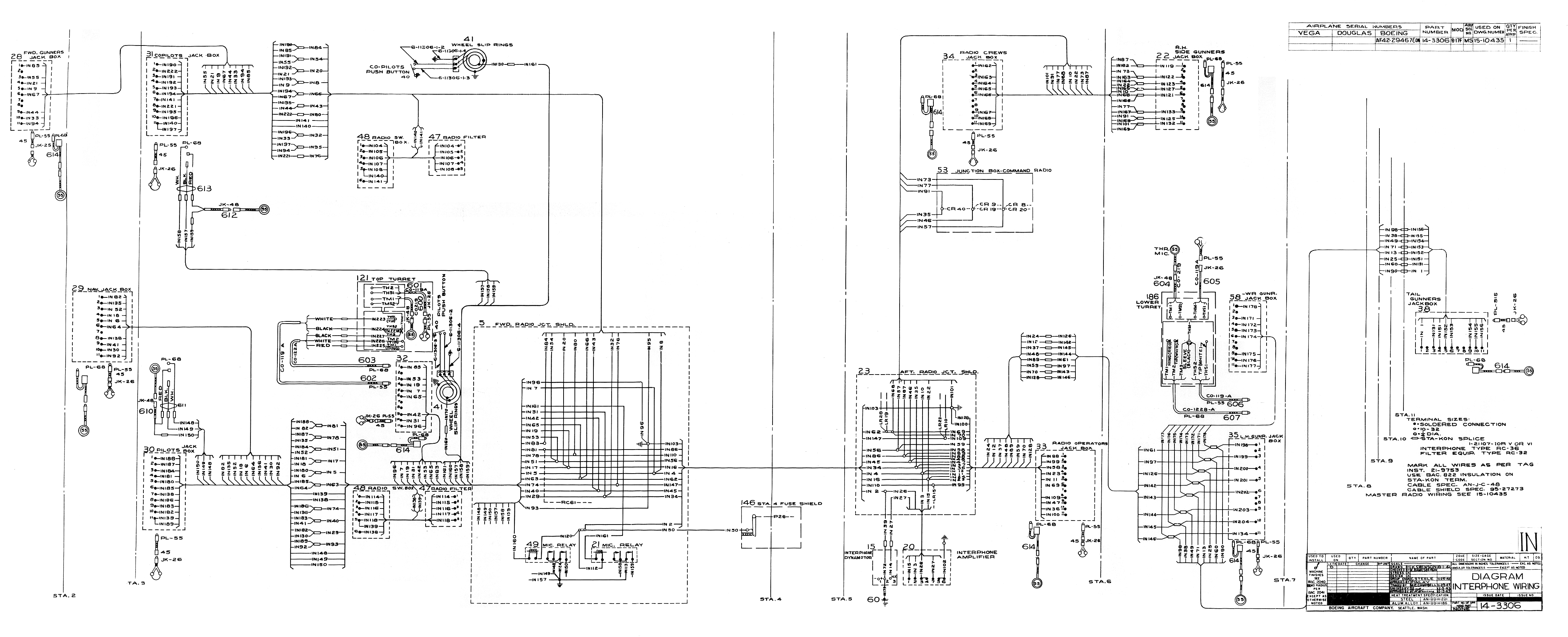
RC-32 Filter & RC-36 Interphone
! ALL BASIC COMPONENTS COMPLETED !
Blueprint 6-7582 Intercom Amplifier
Blueprint 6-9708 Intercom Dynamotor
2x Blueprint 6-13150 Intercom Waist Gunners (Panel)
Blueprint 14-3306 Intercom Wiring Diagram
2x Blueprint 15-10404 Intercom Waist Gunners
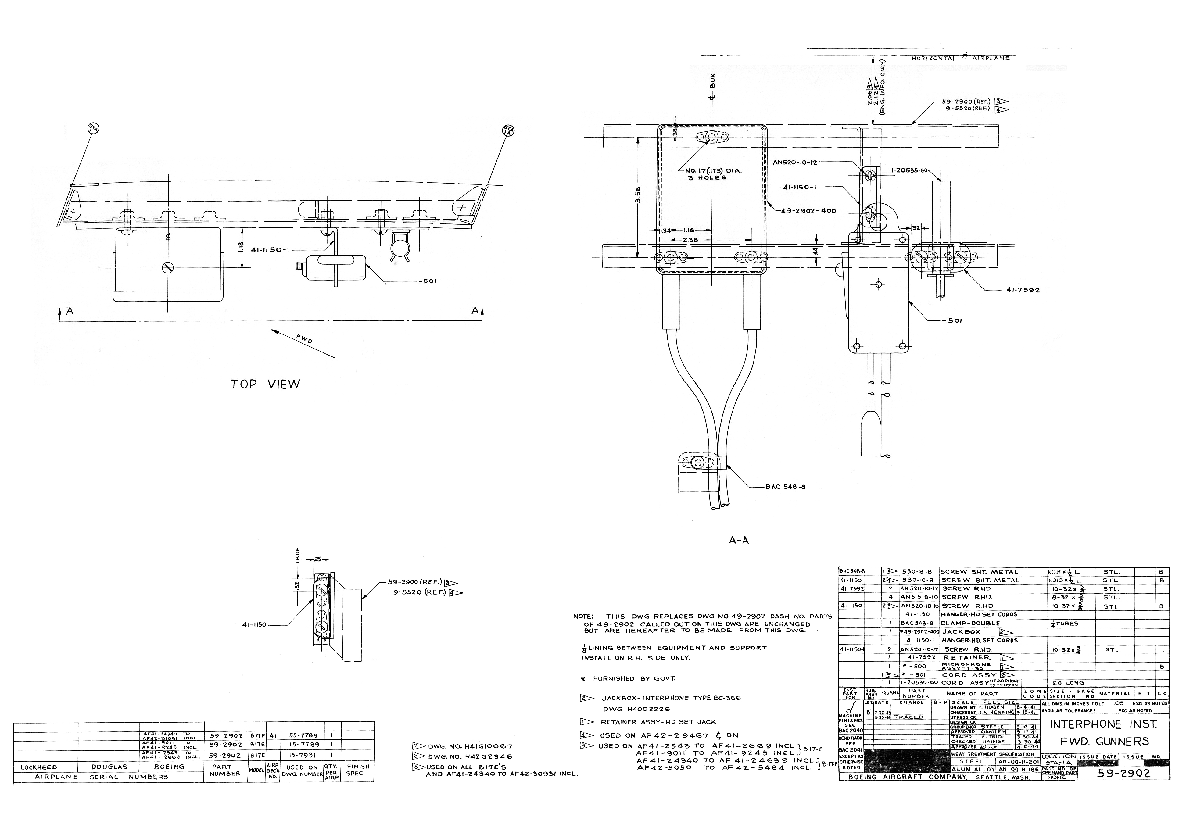
Blueprint 59-2902 Intercom Bombardier
Blueprint 49-3362 Intercom Navigator
Blueprint 64-1741 Intercom Pilot
Blueprint 59-2916 Intercom Co-Pilot
Blueprint 46-9333 Intercom Engineer
Blueprint 59-2875 Intercom Radio Operator
Blueprint 49-3188 Intercom Radio Passenger
Intercom Manual Diagram, Wire Lengths, and Fuses
2x BC-345 Switch Boxes DONATED BY JOE MCKOWEN (GAFFNEY, SOUTH CAROLINA)
BC-347 Amplifier DONATED BY RICHARD BOYENS (HICKORY, NORTH CAROLINA)
10x BC-366 Jack Boxes DONATED BY JOE MCKOWEN (GAFFNEY, SOUTH CAROLINA)
2x FL-5 Radio Filters DONATED BY JOE MCKOWEN (GAFFNEY, SOUTH CAROLINA)
PE-86 Dynamotor DONATED BY JACK ANTONIO (WARNER-ROBINS, GEORGIA)
18 Gauge Wire – 3,219 in. (Approx. 269 ft.)
20 Gauge Wire – 13,551 in. (Approx. 1,130 ft.)
![]()
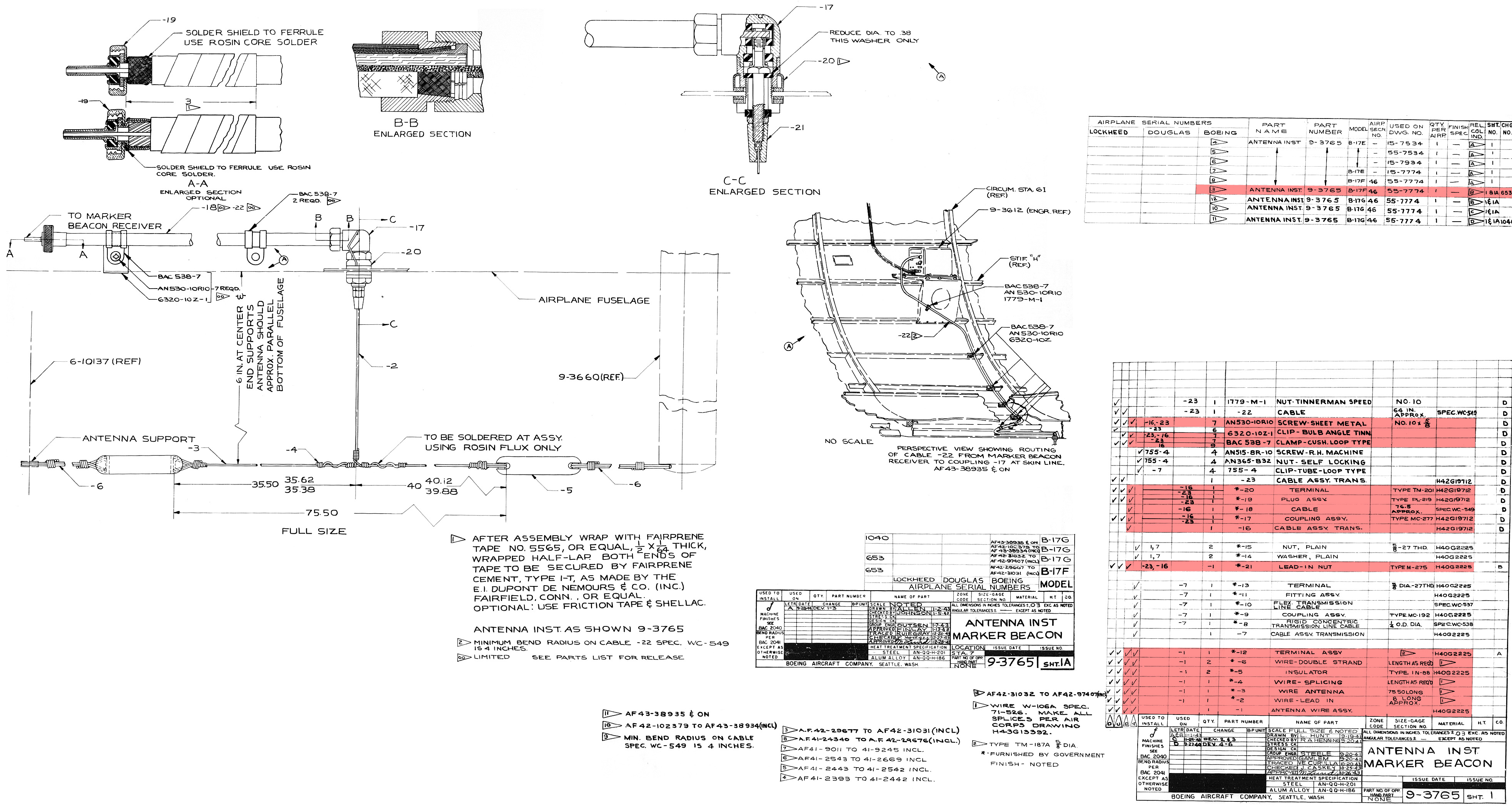
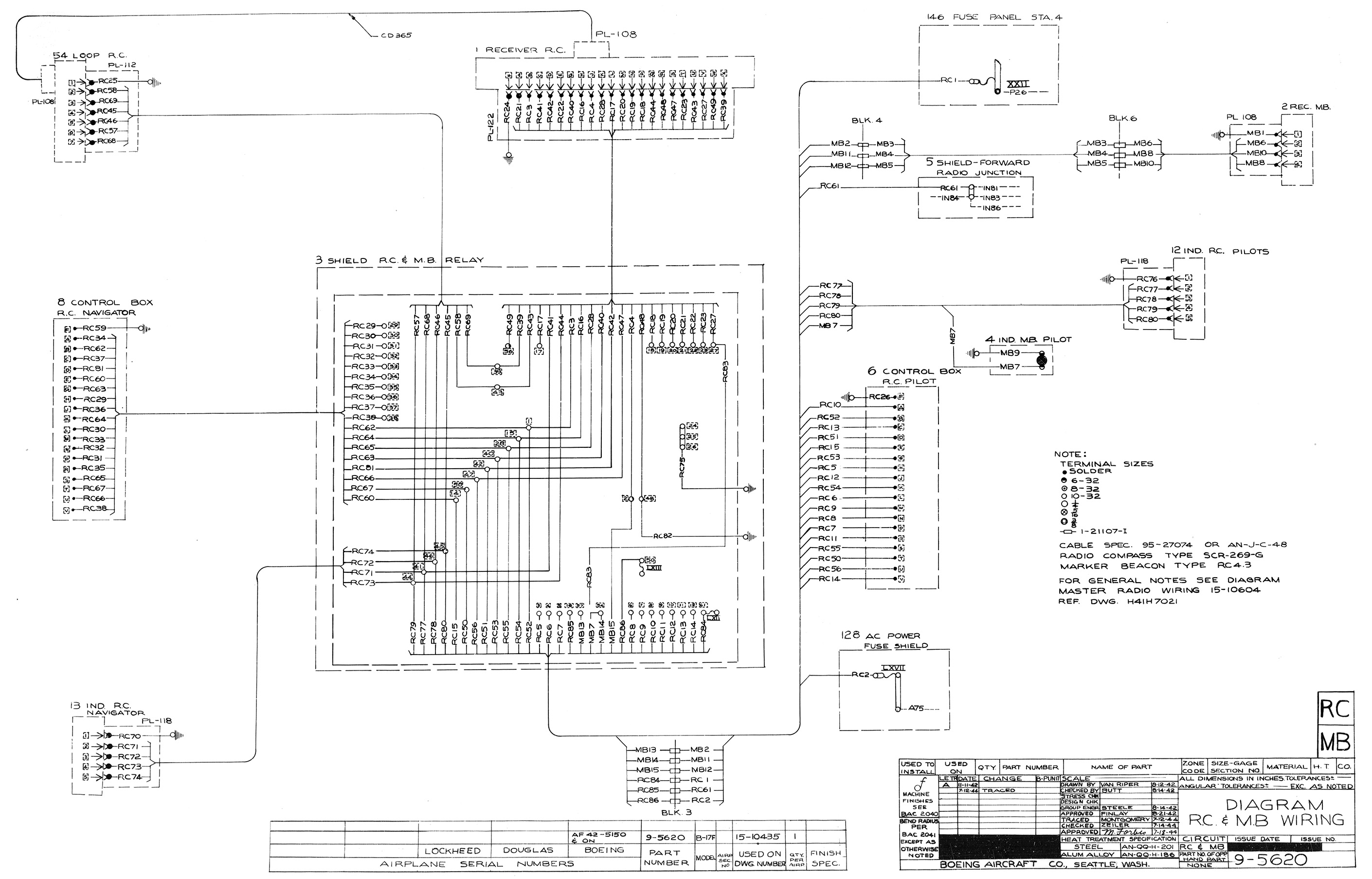
RC-43 Marker Beacon
! ALL BASIC COMPONENTS COMPLETED !
Blueprint 6-10137 Beacon Antenna – Forward Mast
Blueprint 9-3612 Beacon Receiver
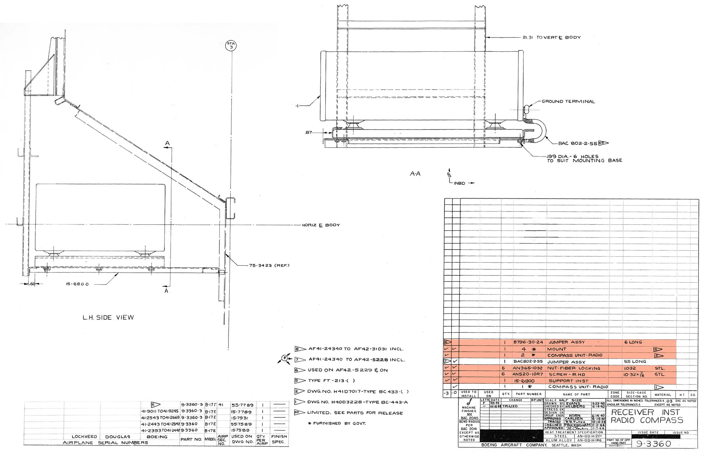
Blueprint 9-3660 Beacon Antenna – Rear Mast
Blueprint 9-3765 Beacon Antenna – Wire
Blueprint 9-5620 Marker Beacon & Radio Compass Wiring Diagram
Marker Beacon & Radio Compass Manual Diagram, Wire Lengths, and Fuses
BC-357 Beacon Receiver DONATED BY ASHEVILLE RADIO MUSEUM (ASHEVILLE, NORTH CAROLINA)
FT-161 Beacon Mount COMPLETED
18 Gauge Wire – 552 in. (46 ft.)
20 Gauge Wire – 1,764 in. (147 ft.)

SCR-211 Portable Frequency Meter
! ALL BASIC COMPONENTS COMPLETED !
BC-221 Frequency Meter (125-20,000 KC) COMPLETED
BG-81 Bag COMPLETED

SCR-269 Radio Compass
Blueprint 3-12787 Radio Compass Coupling
Blueprint 6-9705 Radio Compass Loop
Blueprint 6-10754 Whip Antenna
Blueprint 9-3360 Radio Compass Receiver
Blueprint 9-3713 Radio Compass Antenna Installation
Blueprint 9-5620 Marker Beacon & Radio Compass Wiring Diagram
Blueprint 14-2345 Whip Antenna Lead-In
Blueprint 46-8832 Radio Compass Relay
Blueprint 46-8833 Radio Compass Control (Navigator)
Marker Beacon & Radio Compass Manual Diagram, Wire Lengths, and Fuses
BC-433 Radio Compass (200-400 KC) COMPLETED
2x BC-434 Compass Control Boxes COMPLETED
BK-22 Relay COMPLETED
I-81 Pilot’s Compass Indicator COMPLETED
I-82 Navigator’s Compass Indicator COMPLETED
LP-21 Loop Antenna COMPLETED
Whip Antenna
18 Gauge Wire – 918 in. (Approx. 77 ft.)
20 Gauge Wire – 6,738 in. (Approx. 562 ft.)

SCR-274 Command Radio
! ALL BASIC COMPONENTS COMPLETED !
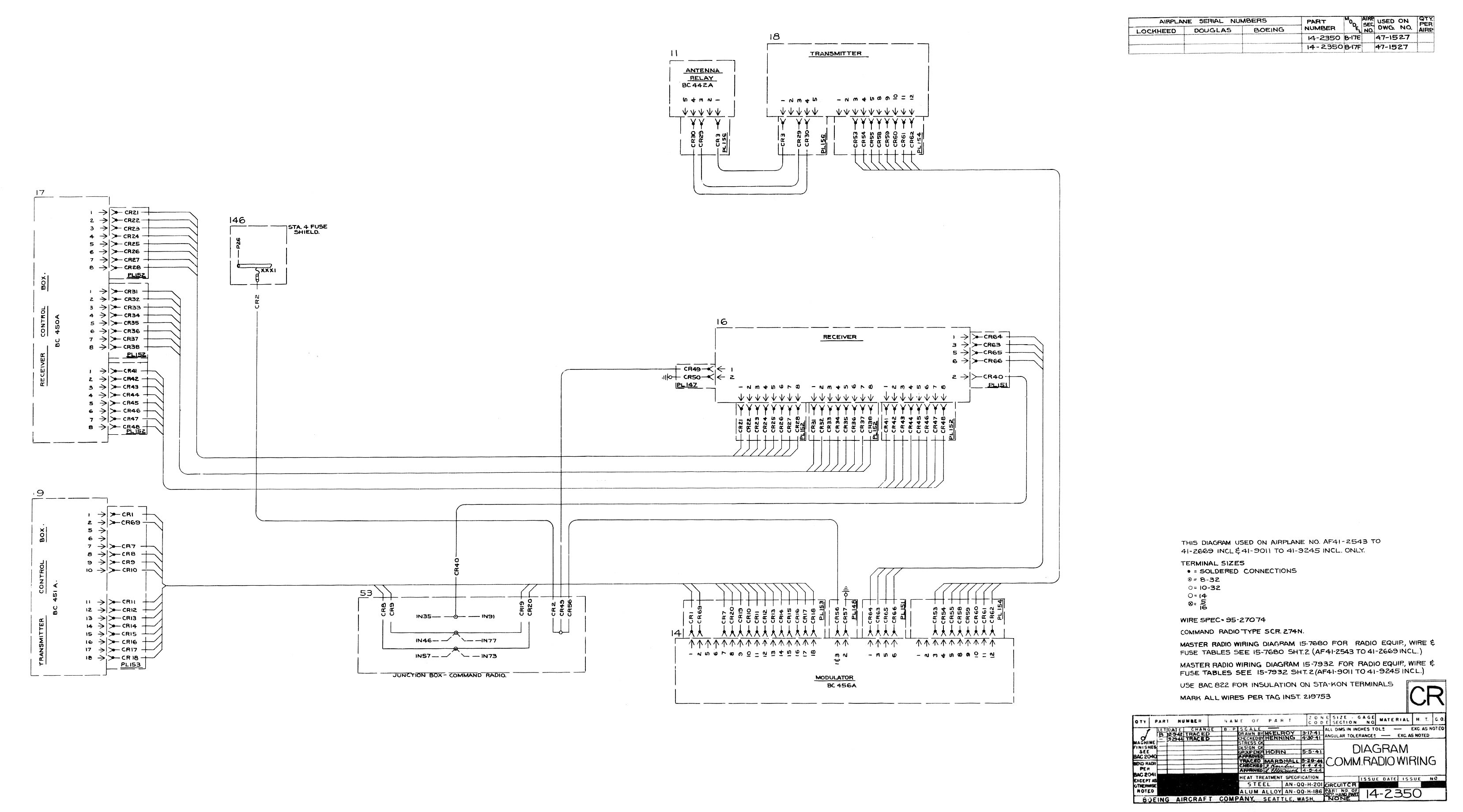
Blueprint 14-2350 Command Radio Wiring Diagram
Blueprint 15-7785 Command Receiver Shelf
Blueprint 15-7786 Command Transmitter Shelf
SPECIAL THANKS TO JACK ANTONIO OF WARNER-ROBINS, GA WHO DONATED A COMPLETE, WORKING SCR-274
BC-442 Relay DONATED BY STEVE WILLIAMS (CLARKSON, KENTUCKY)
BC-450 Receiver Control Box COMPLETED
BC-451 Transmitter Control Box COMPLETED
BC-453 Receiver (190-550 KC) DONATED BY ASHEVILLE RADIO MUSEUM (ASHEVILLE, NORTH CAROLINA)
BC-454 Receiver (3-6 MC) COMPLETED
BC-455 Receiver (6-9.1 MC) COMPLETED
BC-456 Modulator COMPLETED
BC-458 Transmitter (5.3-7 MC) DONATED BY ASHEVILLE RADIO MUSEUM (ASHEVILLE, NORTH CAROLINA)
BC-459 Transmitter (7-9.1 MC) COMPLETED
DM-32 Dynamotor x3 COMPLETED
DM-33 Dynamotor COMPLETED
FT-220 Receiver Rack Mount COMPLETED
FT-221 Receiver Shock Mount COMPLETED
FT-222 Receiver Control Box Mount COMPLETED
FT-225 Modulator Mount COMPLETED
FT-226 Transmitter Rack Mount COMPLETED
FT-227 Transmitter Shock Mount COMPLETED
FT-228 Transmitter Control Box Mount COMPLETED
FT-229 Relay Mount DONATED BY STEVE WILLIAMS (CLARKSON, KENTUCKY)
12 Gauge Wire – 486 in. (Approx. 41 ft.)
18 Gauge Wire – 3,696 in. (308 ft.)
20 Gauge Wire – 7,402 in. (Approx. 617 ft.)

SCR-287 Liaison Radio
! ALL BASIC COMPONENTS COMPLETED !
Blueprint: 6-7189-D Transmitter
Blueprint 6-7193 Tuning Unit Stack
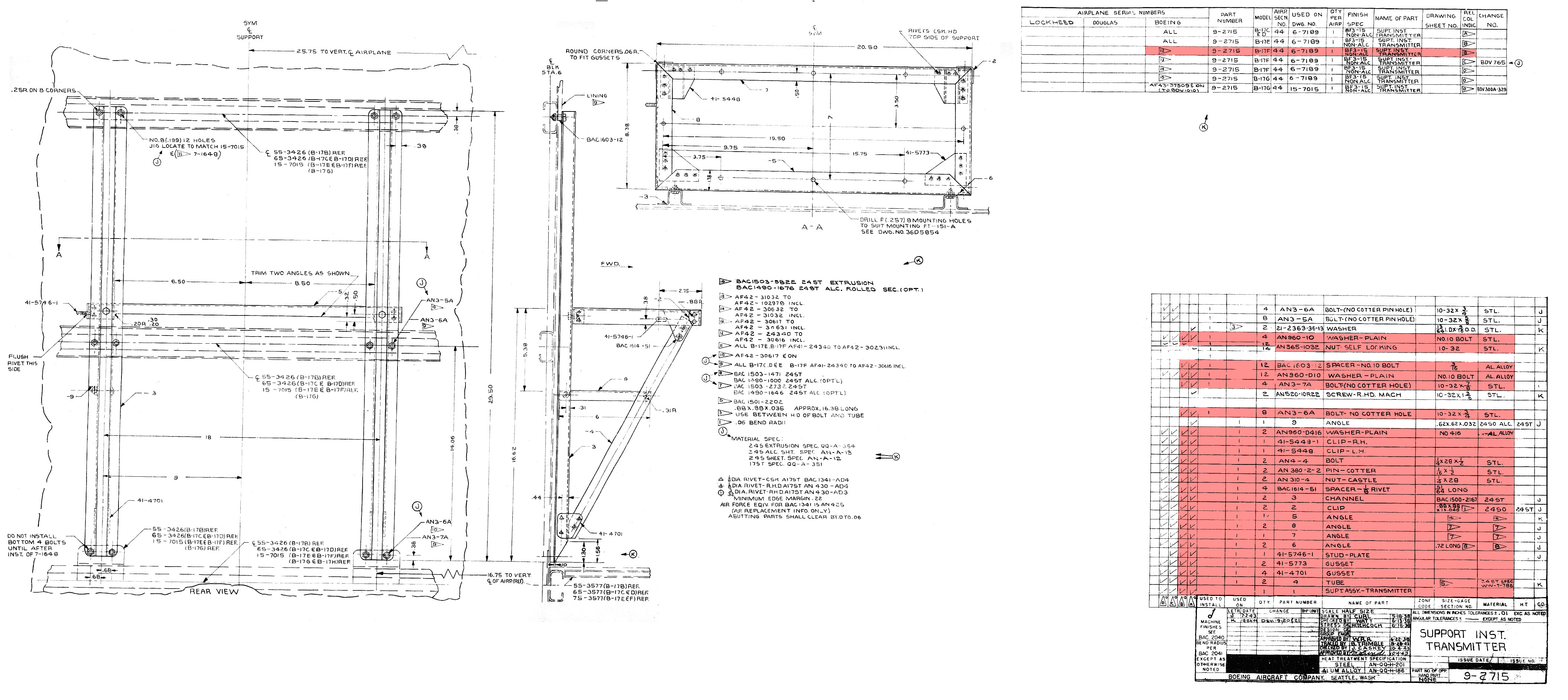
Blueprint 9-2715 Transmitter Shelf
Blueprint 9-5817 Liaison Radio Wiring Diagram
Blueprint 15-8529 Trailing Wire Antenna
Blueprint 15-8548 PE-73 Dynamotor Shelf
Liaison Radio Manual Diagram, Wire Lengths, and Fuses
BC-306 Antenna Tuning Unit COMPLETED
BC-348 Liaison Receiver COMPLETED
BC-375 Liaison Transmitter DONATED BY RICHARD BOYENS (HICKORY, NORTH CAROLINA)
BC-461 Trailing Antenna Control DONATED BY JACK ANTONIO (WARNER-ROBINS, GEORGIA)
6x CS-48 Tuning Unit Cases DONATED BY STEVE WILLIAMS (CLARKSON, KENTUCKY)
F-10 Trailing Antenna Tube DONATED BY DAVID GREEN (VENTURA, CALIFORNIA)
2x FT-115 Liaison Transmitter Mounts COMPLETED
FT-151 Liaison Transmitter Mount DONATED BY RICHARD BOYENS (HICKORY, NORTH CAROLINA)
FT-142 Antenna Tuning Unit Mount DONATED BY STEVE WILLIAMS (CLARKSON, KENTUCKY)
FT-154 Liaison Receiver Mount COMPLETED
J-37 Tuning Key COMPLETED
MC-163 Clamp DONATED BY JOE MCKOWEN (GAFFNEY, SOUTH CAROLINA)
PE-73 Liaison Dynamotor COMPLETED
RL-42 Antenna Reel DONATED BY JOHN B. WILSON (SAPULPA, OKLAHOMA)
SW-224 Knife Switch COMPLETED
TU-5 Tuning Unit (1500-3000 KC) COMPLETED
TU-6 Tuning Unit (3000-4500 KC) COMPLETED
TU-7 Tuning Unit (4500-6200 KC) DONATED BY JEREMEY SCHOTTER (GEORGETOWN, INDIANA)
TU-8 Tuning Unit (6200-7700 KC) DONATED BY SEAN BARTON (SULLIVAN, MISSOURI)
TU-9 Tuning Unit (7700-10000 KC) COMPLETED
TU-10 Tuning Unit (10000-12500 KC) DONATED BY RICHARD BOYENS (HICKORY, NORTH CAROLINA)
TU-26 Tuning Unit (200-500 KC) COMPLETED
WT-7 Counterweight DONATED BY JACK ANTONIO (WARNER-ROBINS, GEORGIA)
6 Gauge Wire – 76.25 in. (Approx. 6.5 ft.)
14 Gauge Wire – 40 in. (Approx. 3.5 ft.)
16 Gauge Wire – 636 in. (53 ft.)
18 Gauge Wire – 1,293 in. (Approx. 108 ft.)
20 Gauge Wire – 879 in. (Approx. 74 ft.)
High Tension Wire – 24 in. (2 ft.)

SCR-522 VHF Radio
! ALL BASIC COMPONENTS COMPLETED !
Blueprint 6-19382 VHF Radio Wiring Diagram
VHF Radio Manual Diagram
*Boeing B-17 setup did not use mount plates but two sets of Lord shock absorbers
**Blueprint 6-19382 is taken from late-war B-17 and may not entirely match Cheyenne-based F-installation
AN-104 Antenna COMPLETED
BC-602 Control Box (100-156 MC) COMPLETED
CS-80 Radio Case COMPLETED
BC-624 Receiver COMPLETED
BC-625 Transmitter COMPLETED
PE-94 Dynamotor COMPLETED
![]()
SCR-578 “Gibson Girl” Portable Emergency Radio
BC-778 Transmitter COMPLETED
BG-109 Bag COMPLETED
BG-110 Bag DONATED BY STAN WOLCOTT (CODY, WYOMING)
Balloon Inflating Tubes DONATED BY ANDY RIVERA (WILMINGTON, DELAWARE)
M-276 Parachute M-390 PARACHUTE DONATED BY STAN WOLCOTT (CODY, WYOMING)
M-277/M-357 Kite DONATED BY GAR HENDRY (MILLCREEK, UTAH)
2s M-278 Balloons DONATED BY ANDY RIVERA (WILMINGTON, DELAWARE)
M-308 Signal Lamp DONATED BY ANDY RIVERA (WILMINGTON, DELAWARE) & STAN WOLCOTT (CODY, WYOMING)
2x M-315 Generator Canisters DONATED BY ANDY RIVERA (WILMINGTON, DELAWARE)
W-147/W-148 Spare Wire

SCR-595 Identification Friend or Foe
! ALL BASIC COMPONENTS COMPLETED !
Blueprint 6-10748 IFF Support
Blueprint 6-10749 IFF Support
Blueprint 6-10756 IFF Insulator
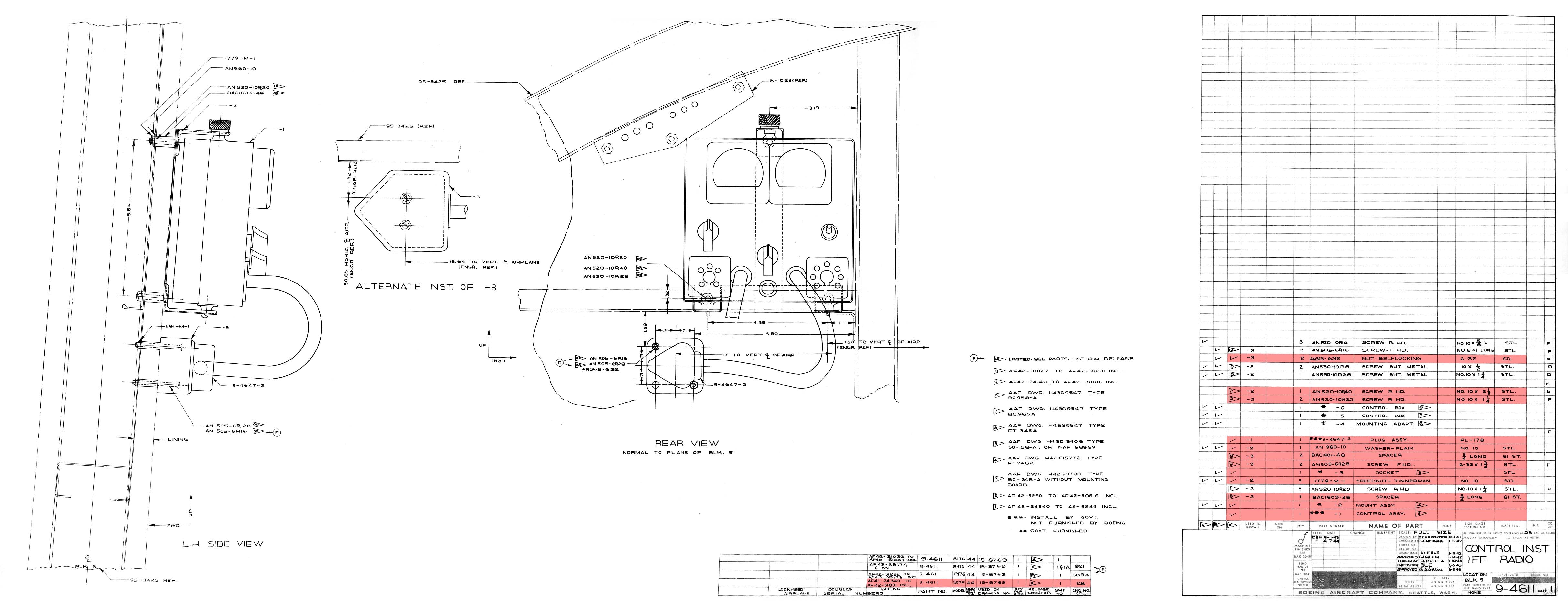
Blueprint 9-4611 IFF Control Installation
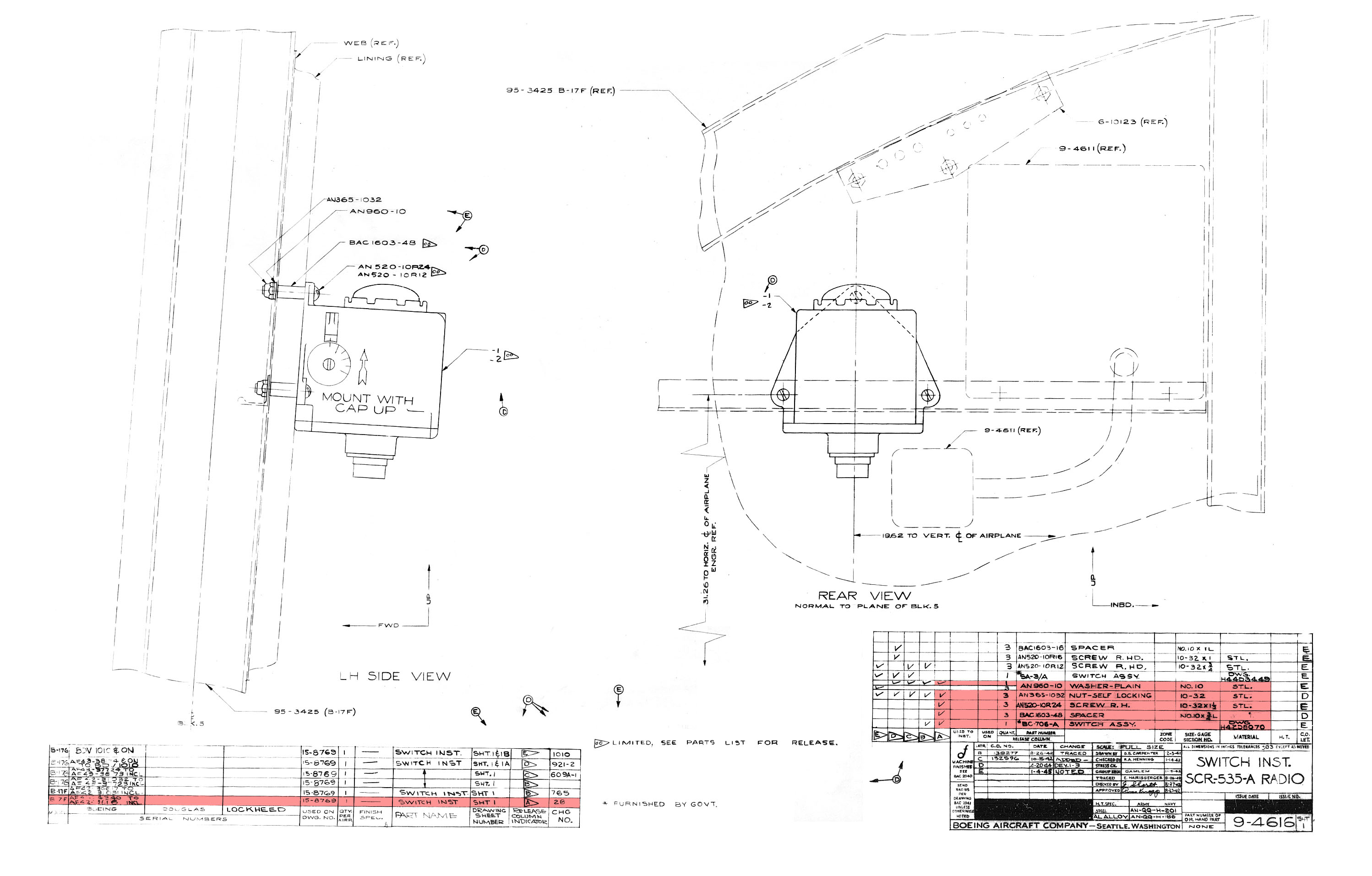
Blueprint 9-4616 IFF Switch Installation
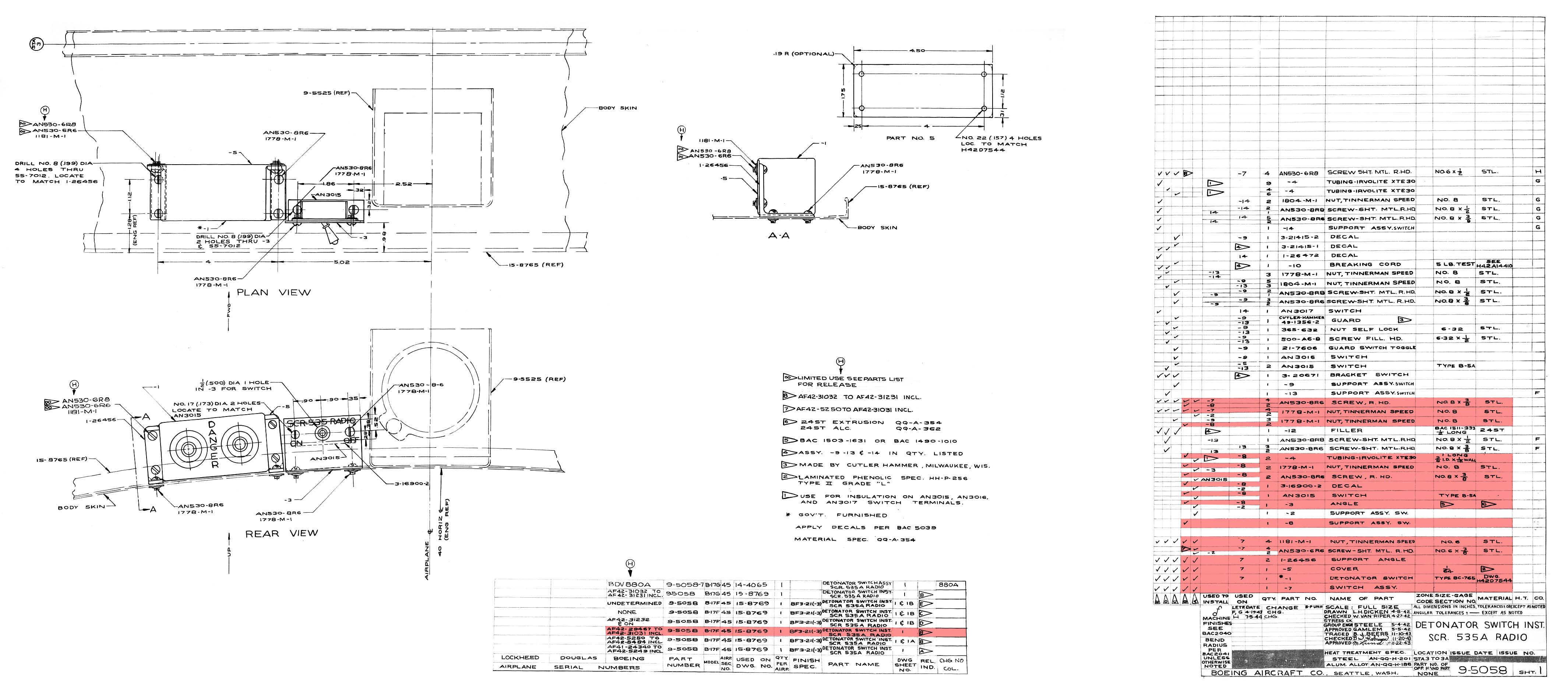
Blueprint 9-5058 IFF Detonator Switch Installation
Blueprint 9-6464 IFF Wiring Diagram
Blueprint 15-8795 IFF Support Assembly
Blueprint 15-8769 Special Radio Equipment
Blueprint 15-8769 Special Radio Equipment (Chart)
Blueprint 15-8796 IFF Installation
Blueprint 15-9760 IFF Antenna
IFF Manual Diagram
SPECIAL THANKS TO JACK ANTONIO OF WARNER-ROBINS, GA WHO DONATED A COMPLETE, WORKING SCR-595
AN-95 Antenna DONATED BY JACK ANTONIO (WARNER-ROBINS, GEORGIA)
BC-706 Inertial Switch COMPLETED
BC-727 Indicator Box DONATED BY JACK ANTONIO (WARNER-ROBINS, GEORGIA)
BC-765 Self Destruct Box DONATED BY JACK ANTONIO (WARNER-ROBINS, GEORGIA)
BC-958 Power Control Box DONATED BY JACK ANTONIO (WARNER-ROBINS, GEORGIA)
BC-965 Selector Control Box DONATED BY JACK ANTONIO (WARNER-ROBINS, GEORGIA)
*BC-966 Transponder DONATED BY JACK ANTONIO (WARNER-ROBINS, GEORGIA)
FT-247 Transponder Mount DONATED BY JACK ANTONIO (WARNER-ROBINS, GEORGIA)
FT-248 Control Box Mount COMPLETED
FT-345 Control Box Mount Plate DONATED BY JACK ANTONIO (WARNER-ROBINS, GEORGIA)